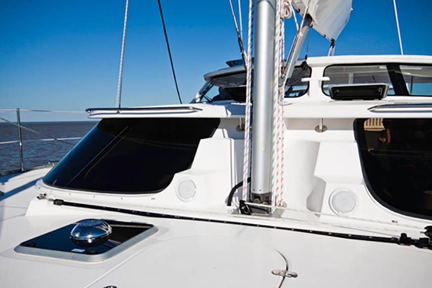
Nothing was arbitrary when designing the Antares 44 sailing catamaran. A combination of often contradictory criteria were weighed and balanced to get the boat design that is performance driven, seaworthy and aesthetically appealing.
From start to finish, technology was a driving force behind building our boats. The power of this technology is phenomenal in its ability to develop shapes and configurations. With these systems, our designers could quickly and accurately perform weight distribution studies using intricate mathematical models that would otherwise take weeks to complete.
So how do you find a balance between performance racing hulls without sacrificing interior accommodations? You use a scale.
The weight of every imaginable item that might theoretically go on board was weighed – from the miles of wire and fuel tanks, to cutlery, books and ice cubes. By assigning a position to these items, he could predict how the boat was going to float with the particular hull shape.
3D Modeling
With a composite model, we can accurately see perspective views. This “real life” view gives us the ability to place a hypothetical person in the boat to gather ergonomic data. These ergonomic reference models in turn help us select every item and its placement on board, from establishing visibility to placement of the dining table and light fixtures. When it comes time to build, we can create cross sections and render 3D surfaces that can then be machined to shape.
Using 3D modeling proved particularly beneficial when designing one of the most challenging design elements on the Antares – placing running rigging from the mast, under the bridgedeck and back up to winch pedestals at the helm and aft deck. Our plans went exactly as modeled and performed as expected.
Design to Development
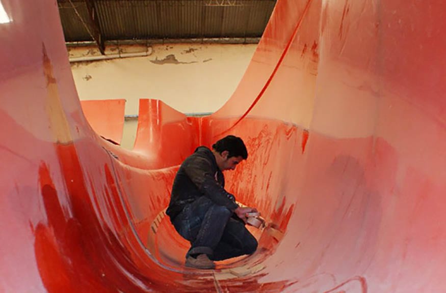
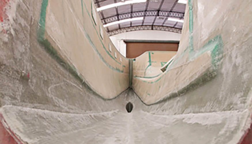
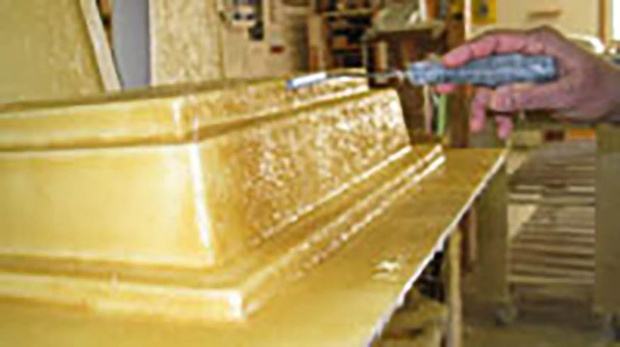
The plans are transformed into a plug that’s constructed of wood, faired and finished. The plug is an exact replica of the finished boat and is used to cast the mold. The Antares hull is comprised of 3 molds – outside left hull, outside right hull, and the inside hulls and bridgedeck. The molds have an orange gel coat finish. By using a dark mold colour, we can ensure an even layer of gel-coat is applied when the required part is layed-up.
The finished mold is buffed, polished, and waxed with bee’s wax before the gel-coat is sprayed. Just as with the plug, the better the quality of the mold finish, the better the quality of the exterior on the Antares.
Gel-coat is a high performance marine resin with excellent durability that prevents blistering. This resin is applied over the mold to create the first layer. When the Antares is released from the mold, the gel-coat is what creates the glossy exterior surface.
Coring & Layup
After the gel-coat, a 1 oz. omni-directional mat is applied to form the skin coat. The skin coat provides adhesion between the gel coat and the layers of fiberglass that follow.
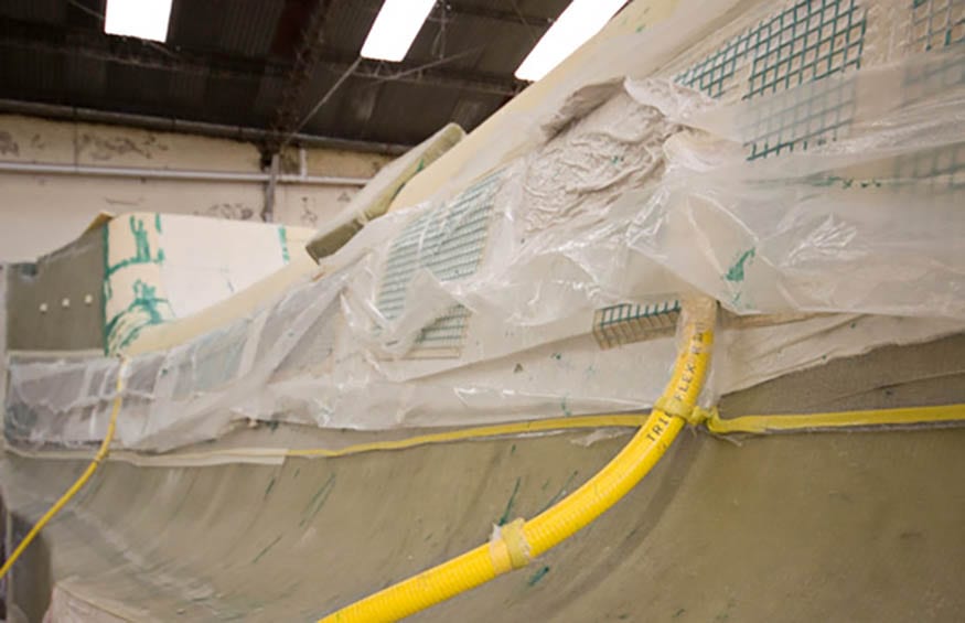
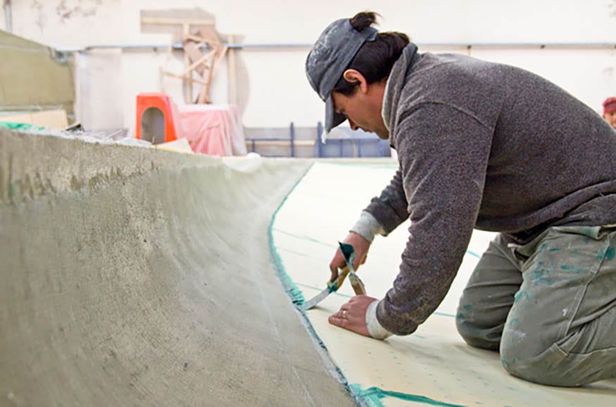
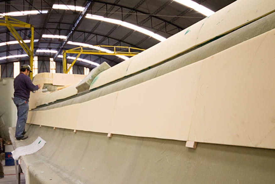
Bonding putty is evenly spread on the hull and foam core is laid on top. Mesh is arranged on top to allow air to be suctioned out from behind a plastic envelope that is applied next. The outer edges of the plastic are then sealed and secured.
When suction is applied to the plastic envelope, 14 lbs/square inch of pressure is applied by the atmosphere, pushing the core firmly against the structural layers. The air travels out through the pinholes in the foam to ensure a secure bond that’s free of any air pockets. This vacuum bagging process assures a 100 percent bond between the structural layers and the core.
We don’t use foam core below the turn of the bilge. Should damage occur below the water line, the solid fiberglass is more easily repaired. Solid fiberglass also facilitates high integrity thruhull installations.
We use a hand layup method to apply all our fiberglass (no chopper gun used). Hand layup requires less resin and results in a lighter, stronger boat.
Hull Assembly
Once the 3 separate components are cored and glassed, the outside hull molds are aligned with the inner hull and bridgedeck mold section. All are clamped securely down their length. The structure is first taped and sealed together with gel-coat. Eight layers of biaxial fiberglass are applied to the seam to create a strong, homogeneous hull structure.
The complete hull is now removed from its mold. The hull structure is then sanded and components are ready to be installed.
Of the 36 pieces required to build the Antares, the hull and deck are the largest. Many small pieces were created to adhere to the “no compromise philosophy” of this boat. For example, the fridge/freezer construction was created specifically for the Antares galley layout.
The fridge door moldings have provisions for insulation thickness and double gaskets to assure an airtight seal. Special attention is required for the fiberglass to adhere smoothly around the sharp corners required for these parts. The result is a custom fridge with better accessibility and use of space.
Bulkheads
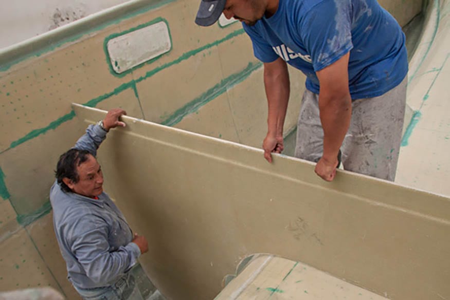
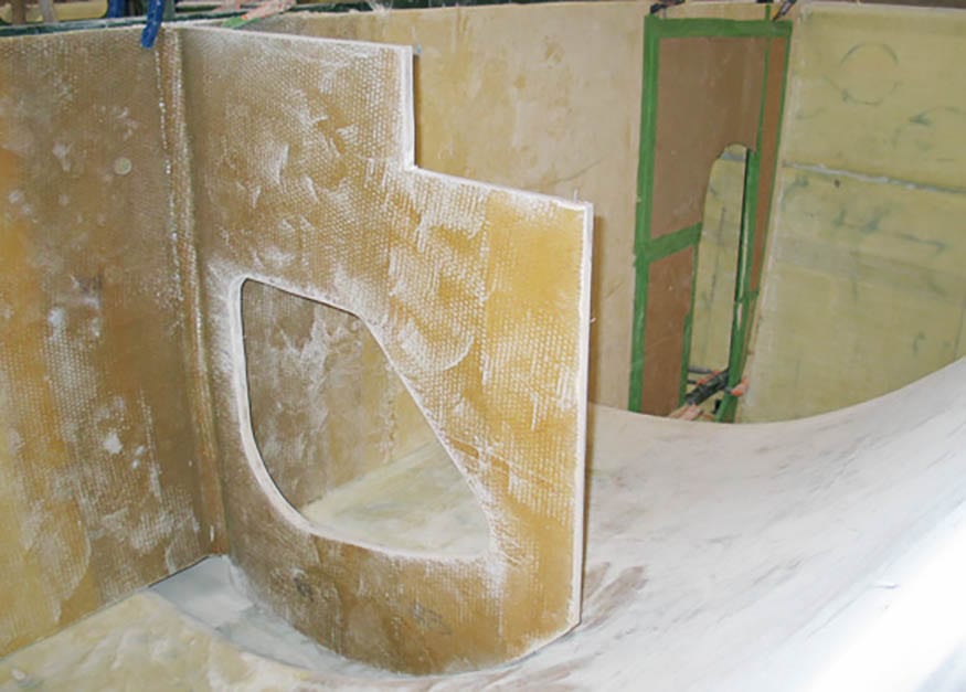
The bulkheads are the first component to go into the completed hull. These structural components require high strength-to-weight ratios. While there are three primary bulkheads that provide structural integrity to the hull, there are also numerous others that are used throughout the hull.
The three major bulkheads are:
- Mast bulkhead: to support the mast & balance the stresses imposed by the rigging
- Companionway bulkhead: forms the division between the cockpit and the saloon
- Steering bulkhead: provides support across the stern and forms the watertight division between the aft cabins and the aft lockers
Foam core is layered on both sides with dry structural fiberglass. A plastic sheet is then placed over the assembly, sealed over the perimeter and connected to a suction hose. Resin is then poured through spigots and carefully distributed throughout the part.
By using the vacuum assisted injection method, we not only use less resin, we’re also ensuring that we get rid of any air bubbles that may cause de-lamination down the road. The materials used, combined with the resin injection process, result in a superior strength bulkhead that’s impervious to water.
Mast Load Calculations
With the vessel weight of the Antares at 22,000 lbs., the expected mast compression loads are about 19,750 lbs. For this experiment, we design with a safety factor of 3 – in other words, we can hold 3 times the expected load amount. We use 60,000 lbs. as a figure for the mast and bulkhead design. The safety factor accounts for calculated loads, extreme conditions, variations in vessel weight, and material property variations.
The spar and rigging loads for catamarans are 1-1/2 times higher than for monohulls of similar sail area due to their high resistance to heeling. We engineer the mast bulkhead much like a gigantic “I-beam”where the bridgedeck and hull are the top and bottom flanges and the bulkhead acts as the web.
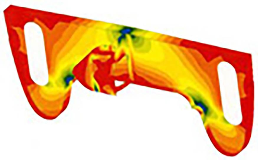
The image above shows the computerized finite element structural analysis of the bulkhead – a value is assigned to the contributions of the deck and bridgedeck and a load is applied to the web, producing patterns of greater and lesser stress.
The small bulkhead in the area immediately below the mast (that runs fore and aft), prevents localized buckling from the loads. While the mast itself isn’t of significant weight, it is the mast compression and the stays pulling up that create the significant loads.
Secondary Bulkhead
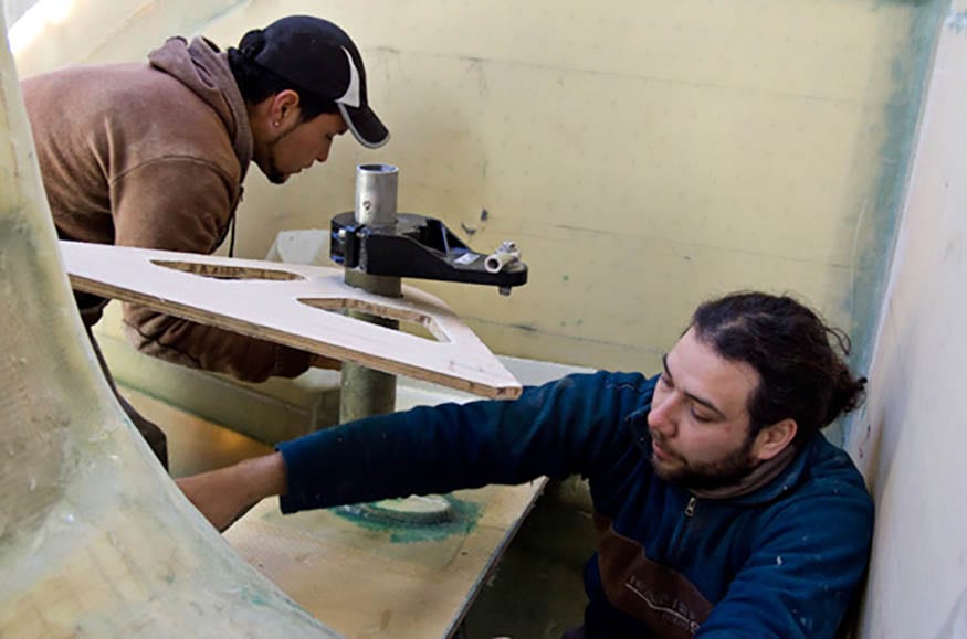
Once the major bulkheads are glassed into place, we glass in the secondary bulkheads. These are area-specific structures such as aft cabins and head modules. These modules are made of several surfaces combined together into one unit and give the overall structure added strength.
Building modules gives us greater control and efficiency over the construction process and consistency in the finished product. By having the modules completed ahead of time we can also minimize the number of people working in the boat at one time leaving less room for error.
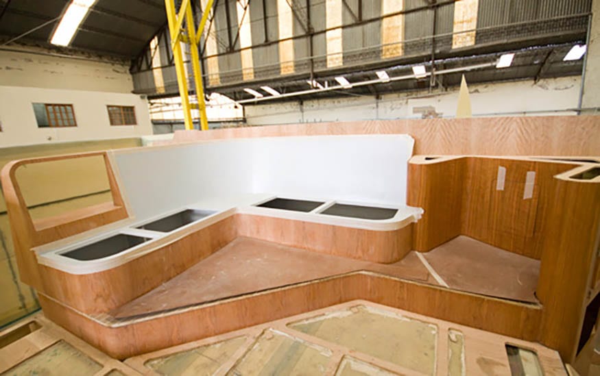
This same principle extends to building wood units such as the salon settee. As with the fiber glass modules, there is greater control of the finished product when constructed on a workbench rather than on the boat.
The materials and methods used require special skills. Using unconventional materials like Tricel – a durable and lightweight honeycomb board sandwiched between 2 layers of veneer – we have perfected distinctive methods working with new materials.
The combination of the materials, the finished shapes and the joinery all contribute to the structural integrity of the modules. Highly engineered and detailed plans guide the construction process to the smallest detail.
Rudder Assembly
The two sides of the custom built rudders are constructed from fiberglass with a core center. This core center significantly reduces the weight of the rudder. The two sides are bonded to extended stainless steel arms that are welded to the rudder stock. The steel is made of 316L stainless that’s highly resistant to corrosion.
The skeg, the tubular casing for the stock, and the rudder are assembled as one unit, adding strength to the overall construction.
The module is held in place at three different areas: at the hull, midway up on a glassed-in shelf, and at the transom step connecting the deck molding. Directional glass running the full length of the skeg also adds strength to the assembly.
Three low-friction UHMW (ultra-high molecular weight) plastic bearings support the stainless stock. This non-friction plastic allows ease of movement within the assembly. The bearings are located at the tiller arm, at the hull, and at the lower rudder and skeg connection.
The skeg makes the rudder stock resistant to bending and allows us to use a lighter stainless steel stock without any sacrifice to strength. In the absence of a skeg, the stock material would have to be stronger and therefore heavier.
Engines
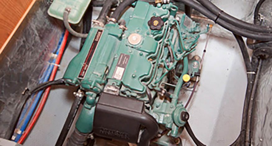
By placing the engines amidships beneath the floorboards and by having all the mechanical equipment in one location – in a compartment forward of the engine – we make accessing the engine and service area easy and convenient. There’s plenty of space for access to the fuel filter, water strainer and pumps.
The shaft drive allows us to place the engines amidships, focussing the center of gravity and reducing the pitching motion of the boat.
At Antares, we’re constantly improving the way we deal with noise produced by the engine and the drive train. In addition to the acoustic insulation (the silver lining pictured above), a sound deadening compound inside the hull where the propeller is located helps to reduce the resonance of the propeller beneath the aft cabins.
We use a dripless face seal instead of a stuffing box. The shaft connects to a rotating stainless steel disc that’s friction fit to a self-aligning carbon-graphite face. This face connects to a rubber reinforced bellow that maintains the right amount of pressure, ensuring a perfect seal. Also, we install flexible couplings and mounts on the engines – which give a vibration cushion and protects the driveline from undue stress.
Deck
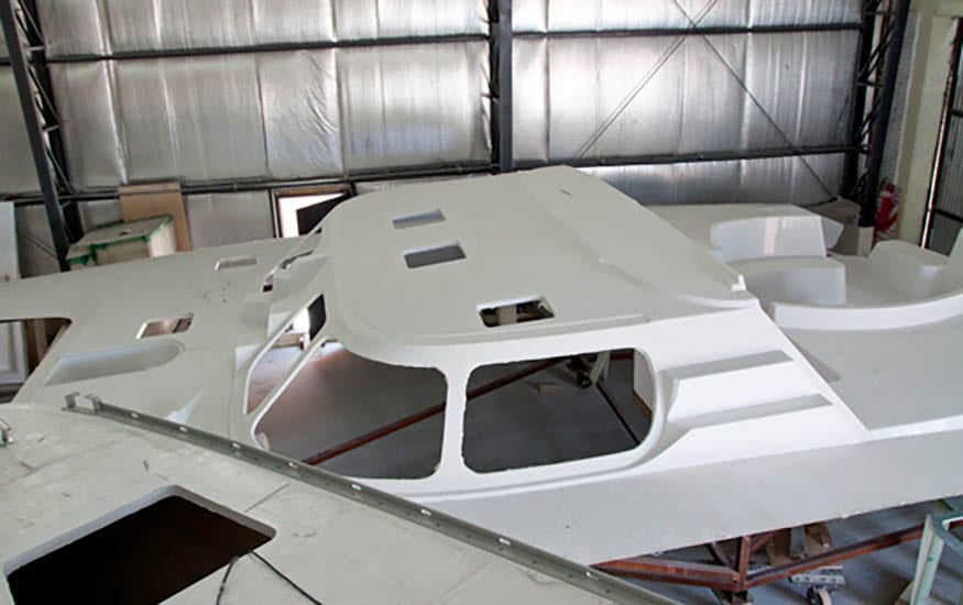
The first step after the deck is layed up is the finishing work of what will be the deckhead of the boat. That’s because the deck is built upside down, much like a (very large) jelly mold. The deck is sanded, the interior area by the mast steps is filled in, and the head liner system is put into place for the vinyl ceiling.
Using a specially designed jig that allows the suspended deck to roll on its axis, the deck is lifted from the mold and rotated to the upright position. The hatch openings and windows are now trimmed out. This also gives us the opportunity for a close-up inspection of the fiberglass finish to make sure the surface is smooth and consistent through out the entire deck.
Fitting the deck onto the hull is another milestone in the 44 construction. This process involves lowering the deck down into place and trimming the structural bulkheads until the deck is in the correct position and its weight is properly distributed.
The toe-rail is then secured onto the deck and is part of the structural joint connecting the outside deck flange to the hull. This strong bond is further reinforced with the layers of multi-directional fiberglass that join the deck to the hull and primary bulkheads on the inside. The external flange hull/deck joint gives you the assurance of added strength at sea as well as hull-scrape protection against the dock. And the resulting 16-inches of unobstructed walkway on the side decks give you easy movement while on deck.
Transom Steps
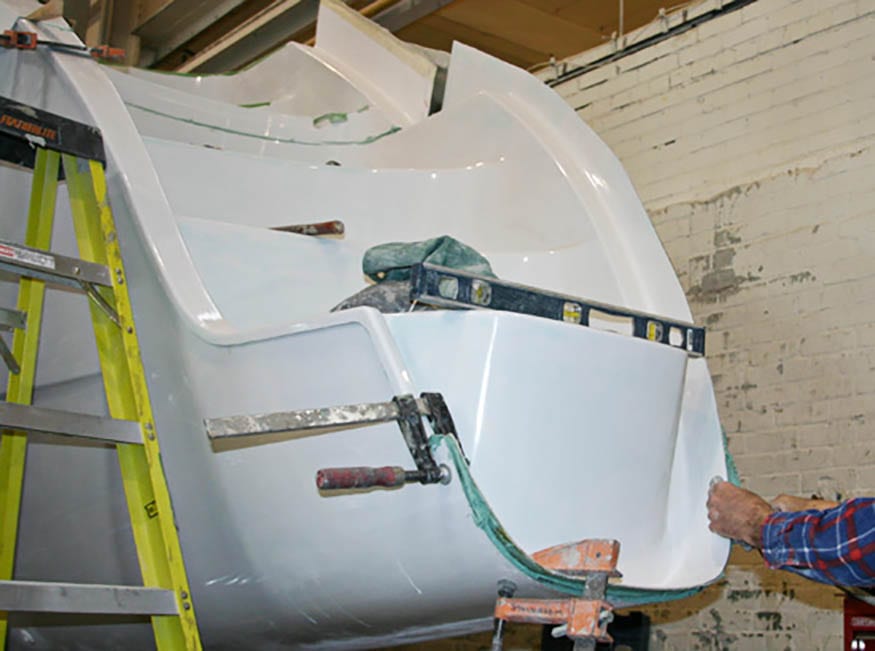
Now that the deck and hull are joined, the final pieces are added to complete the external structure of the Antares – the transom steps. The transom steps are separate molds from the deck molding. This makes it easier to handle the deck molding and gives us access to the steering gear.
The transom steps are carefully positioned onto the stern, measured, leveled and trimmed to ensure a proper fit. The overhanging flange, similar to the joint between the hull and deck, gives us the surface area to allows us to create an even stronger bond to the hull.
Once leveled, the transom steps are glassed into place from both the inside and outside. Where the transom step meets the deck molding, additional fiberglass is used to further strengthen the rudder assembly.
To make a seamless joint on the outside, the gelcoat is first ground down at the joints. A mixture of mill fiberglass (very finely ground fiberglass) is mixed with resin to make a superior bond. Two layers of fiberglass cloth are applied and a layer of gelcoat seals the porous surface. This is then sanded down once again and a final layer of gelcoat is sprayed on to create a seamless seal.
Wiring & Deck Hardware
At this stage, several teams get onboard to complete the building of the Antares. From window and liner installers to electricians and plumbers, the builders work in a well-choreographed method to ensure the workflow process is efficient and uninterrupted.
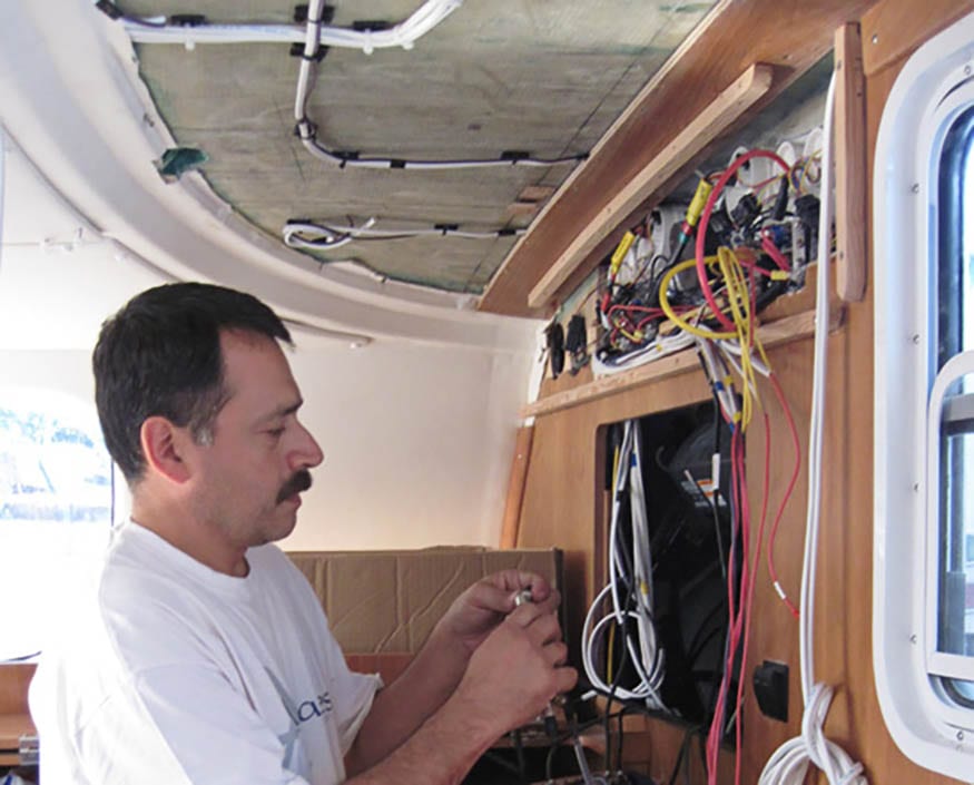
The electrical wires are run along the deck head where the light fixtures will be installed. This process is carefully mapped out to make sure the landings for head liners don’t interfere with the wiring.
The first pieces of hardware to go on the deck are thepulpits and stanchions. The custom-made pulpits are bedded in sealant and securely bolted through the deck. Next, rigging components such as the winches and traveler tracks are bolted onto the deck.
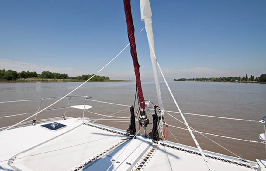
The mast base gets installed and carries the compression loads of the mast. It is bolted into the reinforced fiberglass at the T-junction of the mast bulkhead. This T-junction works to spread the load to the strongest part of the boat. The mast base also organizes the rigging lines that travel down the mast, to the bridgedeck trough and to the foreward sheet winch or to the aft halyard winch.
Hardtop & Crossbeam
Hardtop: The hardtop carries the mainsheet track, which is subject to high loading – in this case, approximately 10,000 lbs. Stainless steel tubular supports are bolted to the deck and bimini to prevent the force of the mainsail from pulling the bimini off.
The traveller track is mounted on a carbon fiber beam that’s laminated onto the hardtop (see cross section illustration below). This carbon fiber structure prevents the beam from bending.
Crossbeam: The same engineering principles used in suspension bridge construction apply to the crossbeam bridle. The vertical forestay loading and to a lesser extent the trampoline and anchoring loadings are resisted by the beam and bridle system.
Tension: The stainless steel bridle wire is in tension counteracting the tendency of the beam to bend upward due to the forestay load. Compression: The A-frame is in compression between the stainless steel wire and the forestay tangs. The beam is also in compression, resisting the pull of the bridle wire. The walkway molding resists horizontal bending of the beam due to rig and tramp loads.
The crossbeam is made of aluminum and anodized for superior corrosion resistance. The crossbeam is connected to the deck and hull using six bolts and FRP reinforcements.
Electrical
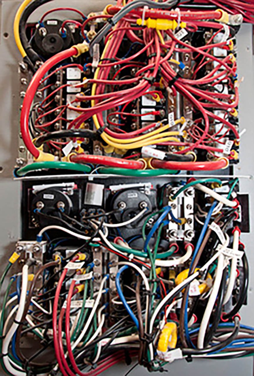
The trail of wire leads back to a stock distribution panel. Because we build our own harnesses in-house, the coils of wire are colour coordinated and follow both ABYC and CE standards for accurate and easy identification.
Dedicated circuits are installed for each unit, such as fresh water pumps, air conditioning, etc. This not only means fewer loads on the breakers, but it also makes the panel both versatile and easy to troubleshoot.
We pay attention to details and make sure all connections below the waterline are double-wall heat shrunk for extra protection. Chafe guard is used to prevent wear and tear from regular vibrations. The wires are also supported every 16 inches so there are no loose wires anywhere on the boat.
Our electrical system is immaculate – all the wires are labeled with numbers that coincide with reference sheets and drawings given to each of our owners. This attention to detail allows us to easily isolate and service any problems down the road.
Interior Finish
Once the majority of the mechanical and electrical systems are in place, the interior details that unify the Antares are installed. The upholstery, vinyl work, and the more than 65 hand-crafted cupboards and drawers are installed.
The vinyl head liner goes in as a finish surface covering up all the wiring and fiberglass. It also acts as a sound insulator. The melded fabric covers any exposed fiberglass, such as on the inside of the cupboards. One the liner is in, the windows are installed. The windows and the deck molding are sanded to give the adhesive a surface to bond to.
To allow for thermal expansion, temporary spacers are used to make sure the sealant bead is at a specified height so the windows can adjust to the minor shifting that will occur. The windows are held in place with lead-shot bags until the adhesive sets. An eyebrow ledge is then installed in place and acts to deflect the sun.
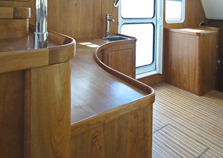
To prevent scratches and dents, the wood cabinet units are some of the last components to go on the boat. The wood modules are glassed in and contribute to the stiffness of the whole structure. From aft to fore, the Antares is furnished with durable cherry-veneer furniture, which adds warmth and richness to the boats atmosphere.
Commisioning
The boat is thoroughly inspected several times before is leaves the plant. Once the final QC inspection is complete, the boat is ready to be launched. Once the boat is in the water, our experienced commissioning teams make sure the boat is finely tuned and seaworthy.
This is also the first time we run the engines. This allows us to check for any manufacturer defects. The steering calibration is also checked to ensure proper rudder alignment.
The mast is stepped and the Antares is ready for its first sea trial. By working closely with the premier mast manufacturer, Antares and Seldén Mast engineered rigging with double diamond arrangement and forward jumper to withstand loads well above typical expectations.
The boat leaves the dock only when the customer is 100% satisfied and feels confident about taking ownership of their new boat.


